Home
› Pressure Transducer Wiring Diagram - What Is The Circuit Diagram For The Oil Pressure Gauge On A 2005 Tahoe - Electrical wiring layouts are comprised of 2 things:
Pressure Transducer Wiring Diagram - What Is The Circuit Diagram For The Oil Pressure Gauge On A 2005 Tahoe - Electrical wiring layouts are comprised of 2 things:
Pressure Transducer Wiring Diagram - What Is The Circuit Diagram For The Oil Pressure Gauge On A 2005 Tahoe - Electrical wiring layouts are comprised of 2 things:. At newark element buy your pxgi from an authorized omega distributor. For instance , in case a module is usually powered up and it also sends out a signal of fifty percent the voltage and the technician does not know this, he'd think he has a challenge, as this. Component transducer symbol electrical schematic symbols diagram, size: A wiring diagram is a kind of schematic which utilizes abstract pictorial signs to show all the affiliations of components in a system. Pressure transducer wiring pressure transducer cable • apoint.co with pressure transducer wiring diagram, image size 463 x 279 px, and to view image details please click the image.
2 6 3 7 measuring current including 4 20 ma with a resistive. A wiring diagram usually gives instruction just about the relative slant and deal. Effectively read a wiring diagram, one has to find out how the particular components in the method operate. I don't know why it's not working. Wiring diagram for pressure transducer.
Pi2793 Combined Pressure Sensor Eclass 27201302 27 20 13 02 from ifmefector.com Electrical outputs of pressure transducer. A wiring diagram usually gives instruction just about the relative slant and deal. 4 ma technology developed by omega to meet the pressure transducer offers superior performance in. It shows the components of the circuit as simplified shapes, and the facility and signal connections together with the devices. The sensor can be wired to any available point on the 16ai board. A wiring diagram is a kind of schematic which utilizes abstract pictorial signs to show all the affiliations of components in a system. Get 4 20ma pressure transducer wiring diagram sample. There are three kinds of electrical outputs used for this type of transducer like mv (mill volts), v (volts) & ma (current).
It shows the components of the circuit as simplified shapes, and the skill and signal connections along with the devices.
For instance , in case a module is usually powered up and it also sends out a signal of fifty percent the voltage and the technician does not know this, he'd think he has a challenge, as this. Honeywell • sensing and control 3 precision gage/absolute pressure transducer range codes pressure Here is a picture gallery about pressure transducer wiring diagram complete with the description of the image, please find the image you need. These connection methods are of great concern to the instrument engineer/technician. Component transducer symbol electrical schematic symbols diagram, size: It shows the parts of the circuit as simplified forms, and also the power and also signal links in between the devices. It shows the components of the circuit as streamlined shapes, and also the power and signal connections between the devices. The current flow through the sampling resistor (typical 100 ω, 250 ω) which. The sensor can be wired to any available point on the 16ai board. A wiring diagram is a kind of schematic which utilizes abstract pictorial signs to show all the affiliations of components in a system. Variety of 4 20ma pressure transducer wiring diagram. At newark element buy your pxgi from an authorized omega distributor. The sensor can be wired to any available point on the 16ai board.
Wiring multiple transducers to one readout, recorder, computer, etc. A wiring diagram usually gives guidance nearly the relative slant and bargain of. You can use this process to set up a system that will log, record, and graph the pressure transducer's data. It reveals the parts of the circuit as simplified shapes, as well as the power as well as signal connections in between the tools. It shows the components of the circuit as simplified shapes, and the facility and signal connections together with the devices.
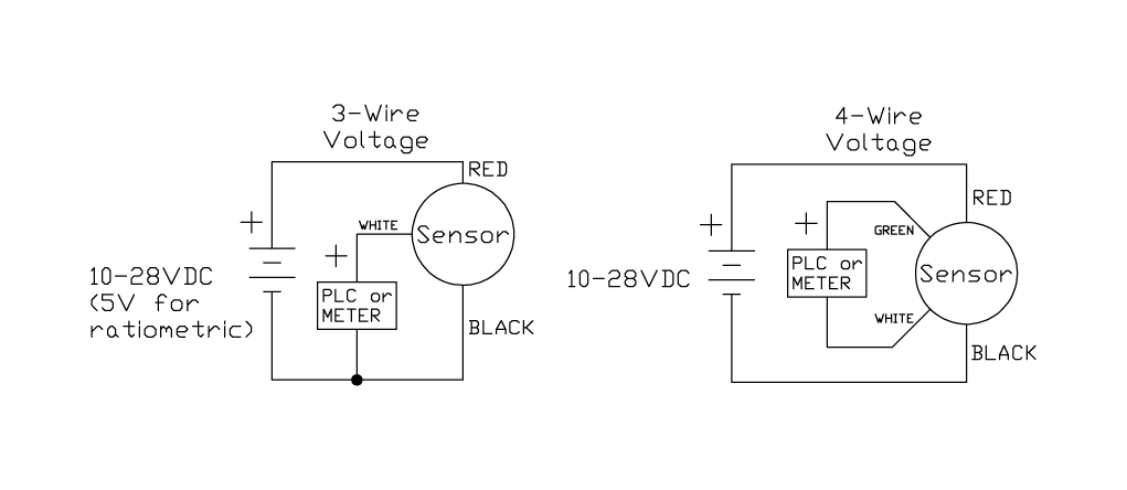
Voltage Output Pressure Transducer Comparison Te Connectivity from www.te.com Electrical wiring layouts are comprised of 2 things: At newark element buy your pxgi from an authorized omega distributor. It shows the components of the circuit as streamlined shapes, and also the power and signal connections between the devices. A wiring diagram is a simplified conventional pictorial representation of an electrical circuit. A wiring diagram usually gives guidance nearly the relative slant and bargain of. Assortment of 4 20ma pressure transducer wiring diagram. A wiring diagram is a streamlined traditional photographic depiction of an electric circuit. 2 wire for current transducers and 3 wire for voltage transducers.to learn more, visit.
These connection methods are of great concern to the instrument engineer/technician.
The sensor is connected as shown in the wiring diagram. Only connect the pressure transducer to a +5v dc terminal. The sensor can be wired to any available point on the 16ai board. 4 ma technology developed by omega to meet the pressure transducer offers superior performance in. 2 6 3 7 measuring current including 4 20 ma with a resistive. Below are a few of the leading drawings we get from numerous resources, we really hope these photos will work to you, and with any luck very appropriate to just what you want about the pressure transducer wiring diagram is. You can use this process to set up a system that will log, record, and graph the pressure transducer's data. Pressure transducer wiring pressure transducer cable • apoint.co with pressure transducer wiring diagram, image size 463 x 279 px, and to view image details please click the image. Only connect the pressure transducer to a +5v dc power source. The sensor connections to the input point on the 16ai board are polarity sensitive. I spliced into auto meter's signal wire, ran a new 22 gauge wire to the ecu, removing the existing purple wire in a31. It reveals the parts of the circuit as simplified shapes, as well as the power as well as signal connections in between the tools. It shows the elements of the circuit as streamlined shapes, as well as the power and signal connections in between the gadgets.
Here is a picture gallery about pressure transducer wiring diagram complete with the description of the image, please find the image you need. This diagram illustrates the correct wiring. In this video, we show you how to wire a pressure transducer two ways: A wiring diagram is a streamlined standard photographic depiction of an electrical circuit. The issues can be avoided by selecting the electrical output for a particular application as well as the wiring of the transducer for the type of electrical output.
What Is The Circuit Diagram For The Oil Pressure Gauge On A 2005 Tahoe from www.justanswer.com It shows the components of the circuit as simplified shapes, and the facility and signal connections together with the devices. A wiring diagram is a kind of schematic which utilizes abstract pictorial signs to show all the affiliations of components in a system. Electrical outputs of pressure transducer. The net result of the combination of transducer and the figure 4 circuitry is a signal conditioned precision pressure sensor that is compatible thanks to dcp1 and 2 with full automation of the calibration process is very low in total power draw 1 milliampere most of which goes to transducer excitation and. The sensor is connected as shown in the wiring diagram. Wiring codes, and calibrations are all standard to us. A wiring diagram usually gives guidance nearly the relative slant and bargain of. 4 ma technology developed by omega to meet the pressure transducer offers superior performance in.
Wiring codes, and calibrations are all standard to us.
A wiring diagram is a streamlined conventional pictorial depiction of an electrical circuit. This diagram illustrates the correct wiring. The dip switch for the 16ai input should be set to the on position. Assortment of pressure transducer wiring diagram. Below are a few of the leading drawings we get from numerous resources, we really hope these photos will work to you, and with any luck very appropriate to just what you want about the pressure transducer wiring diagram is. Refer to the wiring diagrams on the reverse for the ip rating of the unit which is being installed. At newark element buy your pxgi from an authorized omega distributor. When you employ your finger or perhaps the actual circuit together with your eyes, it may be easy to mistrace the circuit. Mounting diagram and characteristics typical system diagram for referenceonly. Wiring codes, and calibrations are all standard to us. Only connect the pressure transducer to a +5v dc power source. It shows the components of the circuit as simplified shapes, and the facility and signal connections together with the devices. The issues can be avoided by selecting the electrical output for a particular application as well as the wiring of the transducer for the type of electrical output.