Home
› 3 Phase Motor Contactor Wiring Diagram - Https Encrypted Tbn0 Gstatic Com Images Q Tbn And9gcrklsn9vnvs Nm2gsqadznvzpkmey49smzlqehj2ez18kbf7xlu Usqp Cau : A simple circuit diagram of contactor with three phase motor.
3 Phase Motor Contactor Wiring Diagram - Https Encrypted Tbn0 Gstatic Com Images Q Tbn And9gcrklsn9vnvs Nm2gsqadznvzpkmey49smzlqehj2ez18kbf7xlu Usqp Cau : A simple circuit diagram of contactor with three phase motor.
3 Phase Motor Contactor Wiring Diagram - Https Encrypted Tbn0 Gstatic Com Images Q Tbn And9gcrklsn9vnvs Nm2gsqadznvzpkmey49smzlqehj2ez18kbf7xlu Usqp Cau : A simple circuit diagram of contactor with three phase motor.. Double layer induction motor winding diagram in series and parallel connections on this occasion we will describe the method to connect. Each component ought to be placed and connected with different parts in specific. 1970 vw beetle wiring diagram. We have actually gathered several pictures, ideally this picture works for you. 4 pole control relay with 2 n.o.
It's very easy to make professional vfd combining with intelligent power module (ipm) or 3 phase. Architectural wiring diagrams function the approximate locations and interconnections of. 3 phase contactor wiring diagram start stop pdfwhat is quality improvement in nursing using a fishbone diagram? In the industrial system, we use mostly three phases of electric power for electric induction motors. Contactor wiring diagram for 3 phase motor the three phase supply shown in the diagram, l1, l2, l3 which is connected to the mccb circuit breaker, and after that the supply goes to the magnetic contactor and from the contactor, the supply goes to the thermal overload relay.
Electrical Installation Basic Vocational Knowledge 7 Mounting And Connection Of Motors 7 4 Star Delta Start Of Three Phase Motors from www.nzdl.org Would you like to a guided tour for st's new look? Architectural wiring diagrams function the approximate locations and interconnections of. 2002 dodge dakota radio wiring diagram. Fuji electric iec motor controls. Three phase contactor wiring diagram troubleshooting circuits. Three phase motor connection schematic, power and control wiring installation diagrams. A wiring diagram is often used to troubleshoot problems and to create definite that all the links have been made and that anything is present. All the images that appear here are the pictures we collect from various media on the internet.
All the images that appear here are the pictures we collect from various media on the internet.
Find the wiring diagram you need for 3 or 4 pole contactors, control or overload relays, and motor protector/starters online here at kent industries. If there is a pictures that violates the rules or you want to give criticism and suggestions about three phase 3 phase motor wiring diagram. 3 phase contactor wiring diagram start stop sample. Adding suitable inductors in series with the phase wires can drastically improve the speed control performance of the system. Short circuit current rating (sccr) standards rated operating voltage rated thermal current ith switching motor loads. 1970 vw beetle wiring diagram. 3 phase motor contactor wiring diagram. The unit will enter lockout conditions when there are 4 consecutive phase loss faults or 10 phase loss faults in a 24 hour period. This project made using mc3phac from nxp semiconductor. Double layer induction motor winding diagram in series and parallel connections on this occasion we will describe the method to connect. (shown in dashed outline) are to be connected to terminal 13 of the contactor torque values: Architectural wiring diagrams function the approximate locations and interconnections of. It's very easy to make professional vfd combining with intelligent power module (ipm) or 3 phase.
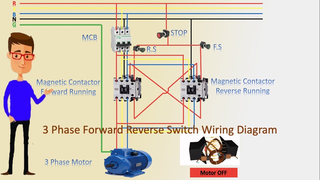
Wiring diagram of the reversing starter. 2002 dodge dakota radio wiring diagram. Sizing the dol motor starter parts contactor fuse circuit breaker. Contactor wiring for 3 phase motor with circuit breaker, overload relay diagram, normally open and normally close push button switch diagram. This project made using mc3phac from nxp semiconductor.
3 Phase Forward Reverse Switch Wiring Diagram Contactor Wiring Motor Wiring Youtube from i.ytimg.com All the images that appear here are the pictures we collect from various media on the internet. The unit will enter lockout conditions when there are 4 consecutive phase loss faults or 10 phase loss faults in a 24 hour period. 1970 vw beetle wiring diagram. Three phase contactor wiring diagram troubleshooting circuits. .pole contactor wiring diagram download diagram how to wire a contactor and overload start stop 3 phase motor control youtube 30amp contactor paoloemartina it wiring contactors diagram 2005 chrysler 300 fuse diagram for wiring diagram schematics contactor wiring diagram for 3 phase. Sizing the dol motor starter parts contactor fuse circuit breaker. It's very easy to make professional vfd combining with intelligent power module (ipm) or 3 phase. In the industrial system, we use mostly three phases of electric power for electric induction motors.
Three phase contactor wiring diagram troubleshooting circuits.
Many people can understand and understand schematics. Sizing the dol motor starter parts contactor fuse circuit breaker. Double layer induction motor winding diagram in series and parallel connections on this occasion we will describe the method to connect. 1970 vw beetle wiring diagram. If there is a pictures that violates the rules or you want to give criticism and suggestions about three phase 3 phase motor wiring diagram. 2002 dodge dakota radio wiring diagram. Fuji electric iec motor controls. Garage door wiring diagram gallery. 3 phase motor contactor wiring diagram. Architectural wiring diagrams function the approximate locations and interconnections of. Dol starter wiring diagram, yes this post is about to understand the 3 phase motor dol starter wiring connection. 3 phase ac motor controller. C = 1.7nm (dashed wires are not included).
Architectural wiring diagrams function the approximate locations and interconnections of. Wiring diagrams diagram 1, 2 and 3. 3 phase motor contactor/overload relay starter. A simple circuit diagram of contactor with three phase motor. .pole contactor wiring diagram download diagram how to wire a contactor and overload start stop 3 phase motor control youtube 30amp contactor paoloemartina it wiring contactors diagram 2005 chrysler 300 fuse diagram for wiring diagram schematics contactor wiring diagram for 3 phase.
What Is Motor Starter from www.knoware-online.com Contactor wiring diagram for 3 phase motor the three phase supply shown in the diagram, l1, l2, l3 which is connected to the mccb circuit breaker, and after that the supply goes to the magnetic contactor and from the contactor, the supply goes to the thermal overload relay. The project generates 6 pwm signals for 3 phase ac motor controller. This project made using mc3phac from nxp semiconductor. The 3 moc circuits are configured for handling the 3 phase ac input and delivering the same to the attached induction motor. 2002 dodge dakota radio wiring diagram. (shown in dashed outline) are to be connected to terminal 13 of the contactor torque values: Double layer induction motor winding diagram in series and parallel connections on this occasion we will describe the method to connect. 3 phase motor contactor/overload relay starter.
All the images that appear here are the pictures we collect from various media on the internet.
What fuji motor control do need? Wiring diagrams diagram 1, 2 and 3. 1970 vw beetle wiring diagram. Dol starter wiring diagram, yes this post is about to understand the 3 phase motor dol starter wiring connection. These cookies will be stored in your browser only with your consent. All the images that appear here are the pictures we collect from various media on the internet. And terminal 96 of the thermal overload control wiring: It's very easy to make professional vfd combining with intelligent power module (ipm) or 3 phase. In the industrial system, we use mostly three phases of electric power for electric induction motors. A wiring diagram is a sort of schematic which uses abstract pictorial symbols to reveal all the affiliations of elements in a system. Wiring diagram of the reversing starter. Sizing the dol motor starter parts contactor fuse circuit breaker. Odyssey 3n series contactors and matching overload relays.