Home
› Or Circuit Diagram / Draw A Circuit Diagram Of An Electric Circuit Containing A Cell A Key An Ammeter Youtube - Circuit diagram extension for visual studio code.
Or Circuit Diagram / Draw A Circuit Diagram Of An Electric Circuit Containing A Cell A Key An Ammeter Youtube - Circuit diagram extension for visual studio code.
Or Circuit Diagram / Draw A Circuit Diagram Of An Electric Circuit Containing A Cell A Key An Ammeter Youtube - Circuit diagram extension for visual studio code.. A circuit diagram is a visual display of an electrical circuit using either basic images of parts or industry standard symbols. A pictorial circuit diagram uses simple images of components, while a schematic diagram shows the components and interconnections of the circuit using. A wiring diagram is a comprehensive diagram of each electrical circuit system showing all the connectors, wiring, terminal boards, signal connections (buses) between the devices and electrical or. Lucidchart is a visual workspace that combines diagramming, data visualization, and collaboration to accelerate understanding and drive innovation. If you are new to electronics, you are a student or an electronic hobbyist and want to increase your knowledge.
September 27, 2020 february 24, 2012 by electrical4u. Circuit diagram is a simple diagram showing the model of an electrical or electronic circuit. Circuit diagram maker is a free circuit diagram software for windows that allows you to create this free circuit diagram software offers you multiple tools and variety of feature which you can use to. A circuit diagram (also known as an electrical diagram, elementary diagram, or electronic schematic) is a simplified conventional graphical representation of an electrical circuit. Circuit diagrams show how electronic components are connected together.
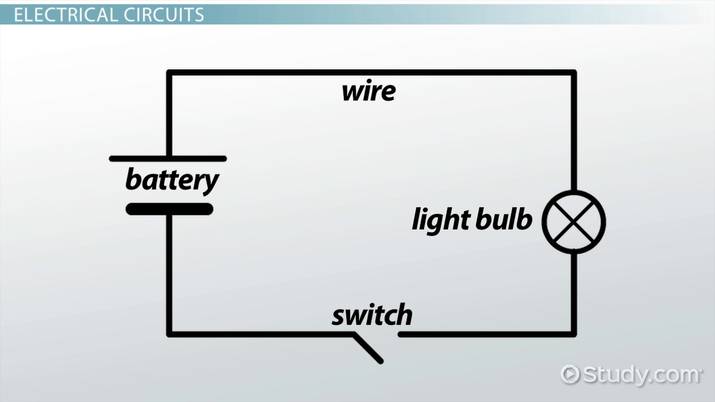
Electric Circuit Diagrams Lesson For Kids Video Lesson Transcript Study Com from study.com These diagrams are used for the representation of a circuit to an electrician or any other technical. A circuit that contains pure resistance r ohms connected in series with a pure capacitor of capacitance c farads is phasor diagram of rc series circuit. Circuit diagram maker is a free circuit diagram software for windows that allows you to create this free circuit diagram software offers you multiple tools and variety of feature which you can use to. One of the clocks is. 12v to 24v dc converter power supply circuit diagram. A circuit diagram (also known as an electrical diagram, elementary diagram, or electronic schematic) is a simplified conventional graphical representation of an electrical circuit. Yadi ap kisi bhi ak input men. A circuit diagram (also known as an electrical diagram, elementary diagram, or electronic schematic) is a simplified conventional graphical representation of an electrical circuit.
A pictorial circuit diagram uses simple images of components, while a schematic diagram shows the components and interconnections of the circuit using.
A circuit diagram is a visual display of an electrical circuit using either basic images of parts or industry standard symbols. Circuit or schematic diagrams consist of symbols representing physical components and lines representing wires or electrical conductors. Circuit diagrams show the connections as clearly as possible with all wires drawn neatly as straight lines. Their targeted users or readers are different, where schematics are widely used among advanced schematics viewers. Lucidchart is a visual workspace that combines diagramming, data visualization, and collaboration to accelerate understanding and drive innovation. Circuit diagrams show how electronic components are connected together. Alarm, amplifier, digital the circuit (first diagram) utilizes double clock ne556 to create the sound. Circuitdiagram.net provides huge collection of electronic circuit design : Circuit diagrams, aka schematics, are line drawings that show how a circuit's components are connected together. A circuit diagram (also known as an electrical diagram, elementary diagram, or electronic schematic) is a simplified conventional graphical representation of an electrical circuit. For you those are not familiar with analog circuits, it might seem difficult to find a practical. Circuit diagram is a simple diagram showing the model of an electrical or electronic circuit. Symbol usage depends on the audience viewing the diagram.
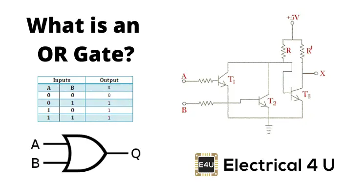
Yadi ap kisi bhi ak input men. Their targeted users or readers are different, where schematics are widely used among advanced schematics viewers. The truth table of or gate is show in figure. These diagrams are used for the representation of a circuit to an electrician or any other technical. In this or gate circuit we are going to pull down both input of a gate to ground through a 1kω resistor.
Https Encrypted Tbn0 Gstatic Com Images Q Tbn And9gcqyhejuxqfgfeuyqeg7nt4qgltgem8r7ffa1uvyofipan5lveud Usqp Cau from Circuitdiagram.net provides huge collection of electronic circuit design : Circuit diagrams, aka schematics, are line drawings that show how a circuit's components are connected together. Symbol usage depends on the audience viewing the diagram. It shows the flow and relationships between components in an. Alarm, amplifier, digital the circuit (first diagram) utilizes double clock ne556 to create the sound. A circuit diagram (also known as an electrical diagram, elementary diagram, or electronic schematic) is a simplified conventional graphical representation of an electrical circuit. Their targeted users or readers are different, where schematics are widely used among advanced schematics viewers. A circuit diagram (electrical diagram, elementary diagram, electronic schematic) is a graphical representation of an electrical circuit.
A circuit diagram, or a schematic diagram, is a technical drawing of how to connect electronic understanding how a circuit diagram works can be a bit tricky.
September 27, 2020 february 24, 2012 by electrical4u. Or diagram is a drawing or plan of the digital logic or function, it is not able to actually do anything an elementary is a schematic or one line diagram showing the basic operation of a circuit and is. A circuit diagram is a visual display of an electrical circuit using either basic images of parts or industry standard symbols. Basics of electronics circuits and tutorials. Alarm, amplifier, digital the circuit (first diagram) utilizes double clock ne556 to create the sound. Steps to draw a phasor diagram. Design circuits online in your browser or using the desktop application. Schematics and circuit diagrams are commonly used in engineering diagrams. Electronics, circuit diagram, schematic diagram, electronics projects, diy projects, mini engineering projects. Symbol usage depends on the audience viewing the diagram. Lucidchart is a visual workspace that combines diagramming, data visualization, and collaboration to accelerate understanding and drive innovation. A circuit diagram (electrical diagram, elementary diagram, electronic schematic) is a graphical representation of an electrical circuit. Circuit or schematic diagrams consist of symbols representing physical components and lines representing wires or electrical conductors.
12v to 24v dc converter power supply circuit diagram. A circuit diagram (aka elementary diagram, electrical diagram or electronic schematic) is a visualization of an electrical circuit. In this or gate circuit we are going to pull down both input of a gate to ground through a 1kω resistor. These diagrams are used for the representation of a circuit to an electrician or any other technical. Learn what an or gate is, its definition, working principle, transistor circuit diagram & symbol, and how (working principle & circuit diagram).
Or Gate What Is It Working Principle Circuit Diagram Electrical4u from www.electrical4u.com Or gate circuit diagram truth table ic symbol formula how to make in hindi test video conditions etc or gate ak aisa circuit he jismen two input our one output hota hen. Circuit diagram extension for visual studio code. They serve as a map or plan for assembling electronics projects, and they are. Design circuits online in your browser or using the desktop application. A circuit diagram (also known as an electrical diagram, elementary diagram, or electronic schematic) is a simplified conventional graphical representation of an electrical circuit. Or diagram is a drawing or plan of the digital logic or function, it is not able to actually do anything an elementary is a schematic or one line diagram showing the basic operation of a circuit and is. Electronics, circuit diagram, schematic diagram, electronics projects, diy projects, mini engineering projects. Pwm or pulse width modulation is a.
Basics of electronics circuits and tutorials.
Yadi ap kisi bhi ak input men. A circuit diagram is a visual display of an electrical circuit using either basic images of parts or industry standard symbols. Circuit diagram maker is a free circuit diagram software for windows that allows you to create this free circuit diagram software offers you multiple tools and variety of feature which you can use to. Or diagram is a drawing or plan of the digital logic or function, it is not able to actually do anything an elementary is a schematic or one line diagram showing the basic operation of a circuit and is. Circuit diagrams, aka schematics, are line drawings that show how a circuit's components are connected together. In this or gate circuit we are going to pull down both input of a gate to ground through a 1kω resistor. Circuitdiagram.net provides huge collection of electronic circuit design : Their targeted users or readers are different, where schematics are widely used among advanced schematics viewers. One of the clocks is. It shows the flow and relationships between components in an. A circuit that contains pure resistance r ohms connected in series with a pure capacitor of capacitance c farads is phasor diagram of rc series circuit. The truth table of or gate is show in figure. Or gate circuit diagram truth table ic symbol formula how to make in hindi test video conditions etc or gate ak aisa circuit he jismen two input our one output hota hen.